Components
The camera electronics consist of commercially available components that are held in place by a mounting frame. This frame consists of M3 threaded rods, PVC-U discs and M3 nuts. In this way, the device can be adapted to new requirements at any time without major tool and assembly work. The following components are used:
- Arducam 2MP Ultra Low Light Camera
- Raspberry Pi Zero 2 W
- UCTRONICS PoE Adapter to Micro USB
- Infrared LEDs and a circuit for dimming them
Camera module
The “2MP Ultra Low Light Camera” module was developed by Arducam for use in low light conditions, such as those that prevail under water. The sensor is also sensitive in the infrared range of light. In combination with infrared light sources, this makes it possible to detect objects in front of the camera, even when there is no ambient light.
Raspberry Pi Zero 2 W
The Raspberry Pi Zero 2 W is used due to its small size, the encoder on the GPU and the available external interfaces. With its four processor cores, this single-board computer has sufficient computing power to operate the camera services. The GPU is fast enough to generate two video streams simultaneously.
UCTRONICS PoE Adapter to Micro USB
This PoE adapter supplies the Raspberry Pi with power and provides the necessary network interface via which all data is exchanged with the outside world.
Dimmable infrared light
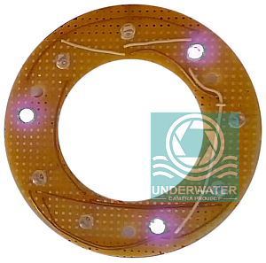
Nine LEDs that emit light in the infrared range (850 nm) are arranged in a circle around the camera module. These LEDs are supplied with 5V from the Raspberry Pi. The series resistors are dimensioned so that a current of 20 mA flows through each LED. Pulse width modulation is used for dimming. The corresponding signal is generated by the Raspberry Pi and a transistor switches the LEDs on and off according to the signal at 30 kHz. The following illustration shows the control electronics.
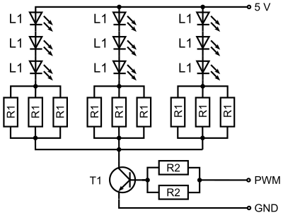
For the resistors 100 Ω is used for R1 and 10 kΩ for R2. The function of the LEDs was checked using a “Depstech D08” webcam. This is possible because the webcam’s sensor has a residual sensitivity in the infrared range of light. The following photo shows an image of the infrared lighting with the aforementioned webcam. Three of nine LEDs are switched on. The circuit used and the distribution of the LEDs ensure that if one LED fails, not all LEDs fail and the light continues to be distributed as evenly as possible.